Christopher Trumbour
2015-08-05 15:55:18 UTC
<Loading Image...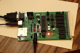 >
>
<Loading Image...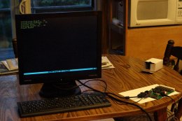 >
>
And it worked first go!
Though I am not entirely sure about the LEDs. The markings were, uh, a
little confusing? Since everyone else apparently has the Cathode side
marked with a flat edge on the circle marking on the PCB, but the PropIO
board (and the N8VEM SBC V2, and the ECB Backplane) have a square and
rounded solder pad with a pair of lines next to the rounded pad... so I put
the Cathode lead into the round pad. +5V lights when powered separately,
but +3V3 doesn't???
Also, let me just say that SMD soldering sucks. It really does. And I don't
like how there's nothing else supporting the SD Card slot aside from the
soldering. Why couldn't they have like, snap-in pins in the guide holes to
keep it secure?
 >
><Loading Image...
 >
>And it worked first go!
Though I am not entirely sure about the LEDs. The markings were, uh, a
little confusing? Since everyone else apparently has the Cathode side
marked with a flat edge on the circle marking on the PCB, but the PropIO
board (and the N8VEM SBC V2, and the ECB Backplane) have a square and
rounded solder pad with a pair of lines next to the rounded pad... so I put
the Cathode lead into the round pad. +5V lights when powered separately,
but +3V3 doesn't???
Also, let me just say that SMD soldering sucks. It really does. And I don't
like how there's nothing else supporting the SD Card slot aside from the
soldering. Why couldn't they have like, snap-in pins in the guide holes to
keep it secure?
--
You received this message because you are subscribed to the Google Groups "N8VEM" group.
To unsubscribe from this group and stop receiving emails from it, send an email to n8vem+***@googlegroups.com.
To post to this group, send email to ***@googlegroups.com.
Visit this group at http://groups.google.com/group/n8vem.
For more options, visit https://groups.google.com/d/optout.